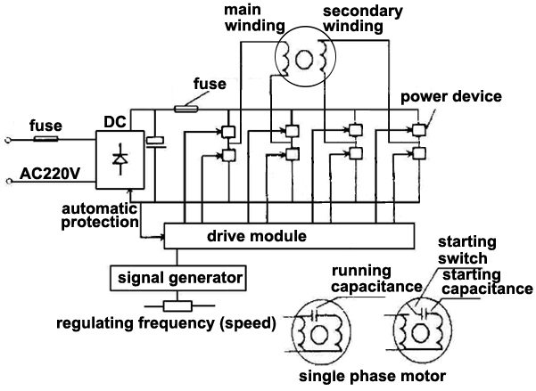
Three phase motor power control wiring diagrams. Assortment of 3 phase 6 lead motor wiring diagram.
The motor will supply the same amount of power but with a different load amperage.

You can find out more Diagram below
3 phase 6 wire motor wiring diagram. Three phase wiring diagrams always use wiring diagram supplied on motor nameplate. Assortment of 3 phase 6 lead motor wiring diagram. Electric motor wire marking connections.
Wiring a baldor motor can at first glance look to be a very intimidating task. You can also find other images like images wiring diagram images parts diagram images replacement parts images electrical diagram images repair manuals images engine diagram images engine scheme diagram images. For example use a red wire nut to connect two 12 gauge wires.
How to wire a baldor 3 phase motor. Now for the purposes. A wiring diagram is a streamlined conventional photographic representation of an electric circuit.
Cap it with a wire nut. How the wires are interconnected dictates the voltage being supplied to the motor. Yet with the help of this step by step guide this task will be become as easy as counting to five.
Three phase motors single speed. If you need to remove any file please contact original image uploader. For specific leeson motor connections go to their website and input the leeson catalog in the review box you will find connection data dimensions name plate data etc.
It reveals the elements of the circuit as streamlined forms and also the power and signal links in between the tools. 3 phase 6 wire motor wiring diagram you are welcome to our site this is images about 3 phase 6 wire motor wiring diagram posted by ella brouillard in 3 category on oct 18 2019. W2 cj2 ui vi wi w2 cj2 ui vi wi a cow voltage y high voltage z t4 til t12 10 til t4 t5 ali l2.
Six wire three phase electric motors are dual voltage motors. If there is a neutral wire in the conduit or cable supplying the motor it is unused for the motors three phase wiring. Capacitor motor single phase wiring diagrams always use wiring diagram supplied on motor nameplate.
The supply voltage is either 240 volts alternating current vac or 480 vac. It reveals the elements of the circuit as streamlined forms and also the power and signal links in between the tools. Three phase motor power control wiring diagrams 3 phase motor power control wiring diagrams three phase motor connection schematic power and control.
A three phase motor is more efficient than a single phase motor because of the peculiarities of alternating current ac. Wire a three phase motor in either a wye configuration or a delta configuration in high or low voltage using a nine lead set up.


0 comments:
Post a Comment