If 10 wires between the air handler and the heat pump is not possible w1 and w2 can be combined at the ah. Affinity series single package gaselectric air cooled air conditioners 2 thru 5 nominal ton.
Compressor delay change to on for delay when going into and out of defrost.

You can find out more Diagram below
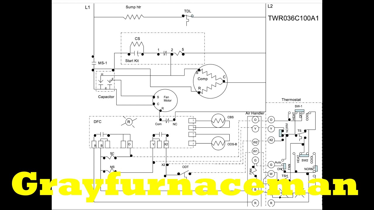
York compressor wiring diagram. David talks about basic compressor wiring. Typical wiring diagram notes all field wiring to be accomplished following city local andor national codes in effect at time of installation of this unit. Ground the compressor and apply 12 volts to the wire.
Nortek global hvacreznor does not endorse any field changes to factory wiring schemes. York onboard air compressor. 1 1 compressor s1 01503998001 s1 01503999001 s1 01504066001 s1 01503812000.
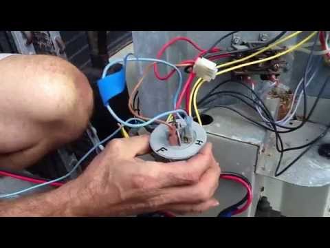
The compressor with standard. Using the diagram above you can see that each compressor has a different detail to its shaft that helps identify it. E1rd series 13 seer x3 heat pump r22 style b.
York retail system specific wiring diagrams. The york compressor will have a single wire coming off of it. Please note that lookup by sales order and purchase order currently only applies to products produced 2014 and earlier.
2 how to get the electrical wiring for air conditioning systems. 37 diagram wiring 125830 125830 125830 125830 1 38 kit motor mounting acorn nuts s1 36390117700 s1 36390117700 s1 36390117700 s1 36390117700. The vsd powercontrol panel includes main power connections vsd and fan motor contactors current overloads and factory wiring.
Want to find some information on your unit. All exposed power wiring is routed through liquid tight uv stabilized non metallic conduit. View and download york dnp024 technical manual online.
This material is for professional use only and is intended to be used only as reference material by licensed contractors when installing or servicing reznor equipment. Rheem goodman trane carrier lennox tempstar and most other off brand units all use the same style of compressor which makes wiring easier to understand across different manufactures. Usually the electrical wiring diagram of any hvac equipment can be acquired from the manufacturer of this equipment who provides the electrical wiring diagram in the users manual see fig1 or sometimes on the equipment itself see fig2.
You should hear a click from the clutch engaging. York system wiring diagrams wd 2. Shirts decals.
In the search box below enter a unit serial number and find it. Selection of frame 36 and larger are standard dual point with single point option.


0 comments:
Post a Comment